
Installing the dedicated caster stand
 | Doing so may cause injury. | |
This machine may fall over. Be sure to install the attached fixing parts. To install any of the three expansion trays, be sure to mount the anti-tip feet. | ||
This is a stand with casters for moving this machine.
It also comes with anti-tip feet to avoid the risk of tipping. It is recommended to use it when the expansion tray is installed.
A Phillips-head screwdriver and a flat-head screwdriver are required to install the caster stand.
![]()
To install any of the three expansion trays, be sure to install the dedicated caster stand, the anti-tip feet and the attached fixing parts to avoid the risk of tipping.
The packing box and buffer material are required to ship the dedicated caster stand. Do not discard them, but store them safely.
Model: BOD-S3 |
|---|
| Doing so may cause injury. | |
This machine weighs approx. 30 kg, so be sure to have it lifted by at least 2 persons. | ||
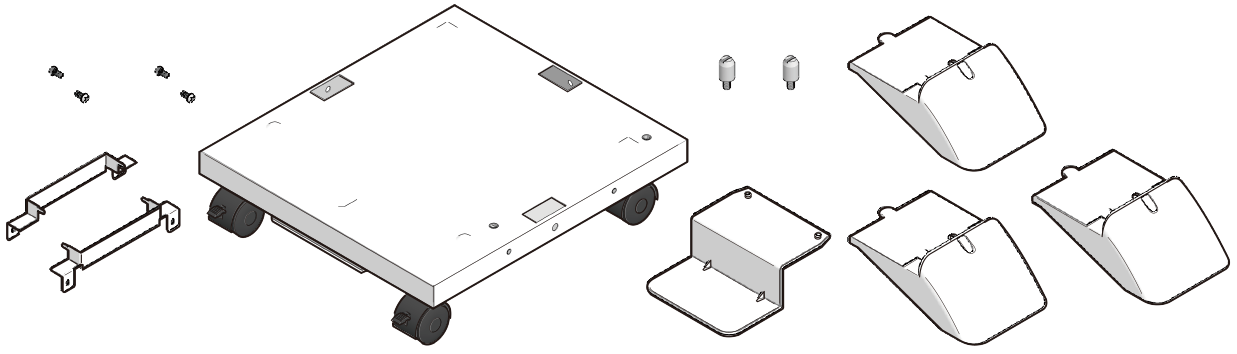
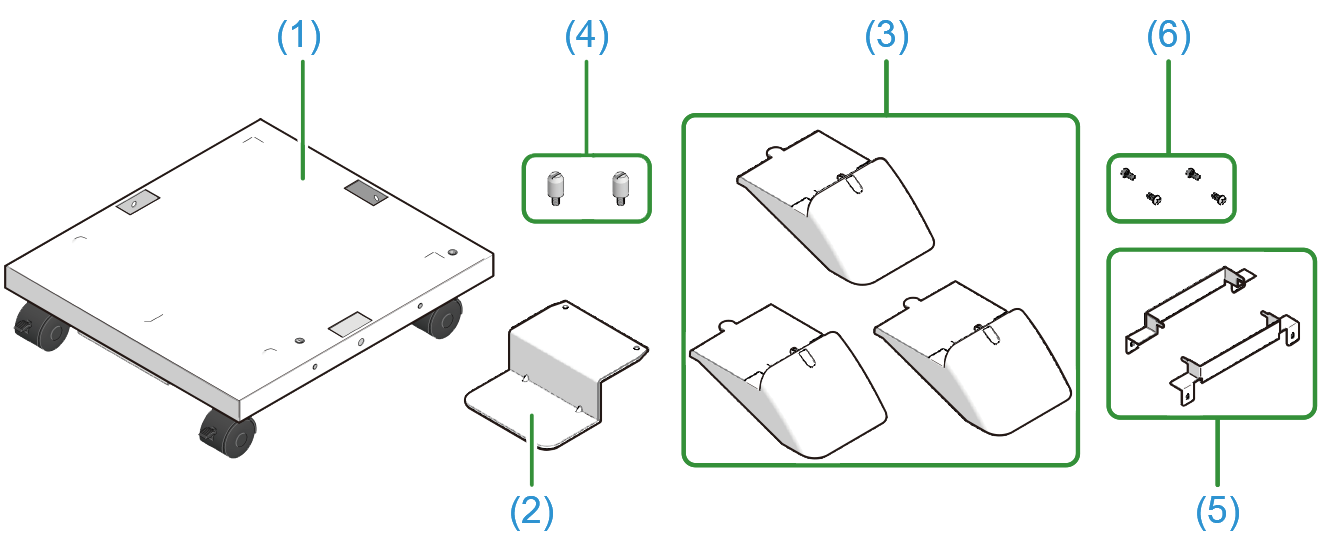
Check that you have all the parts for the dedicated caster stand.
- Main unit
- Anti-tip foot a
- Anti-tip feet b (x 3)
Positioning pins (x 2)
- Metal fixtures of the caster stand (x 2)
- Screws (x 4)
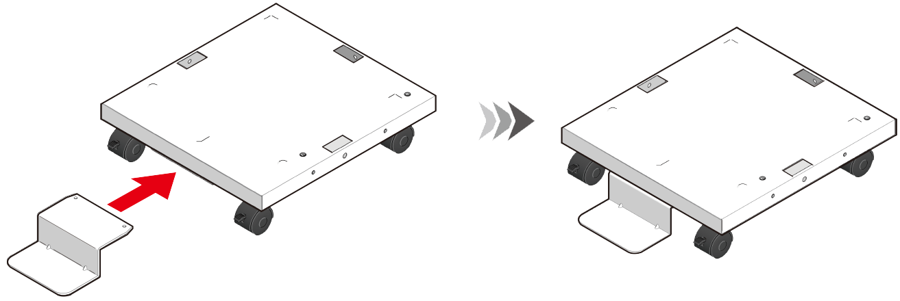
Mount the anti-tip foot a on the front of the dedicated caster stand.
- Then, mount the anti-tip feet b (x 3) to both sides and the back.
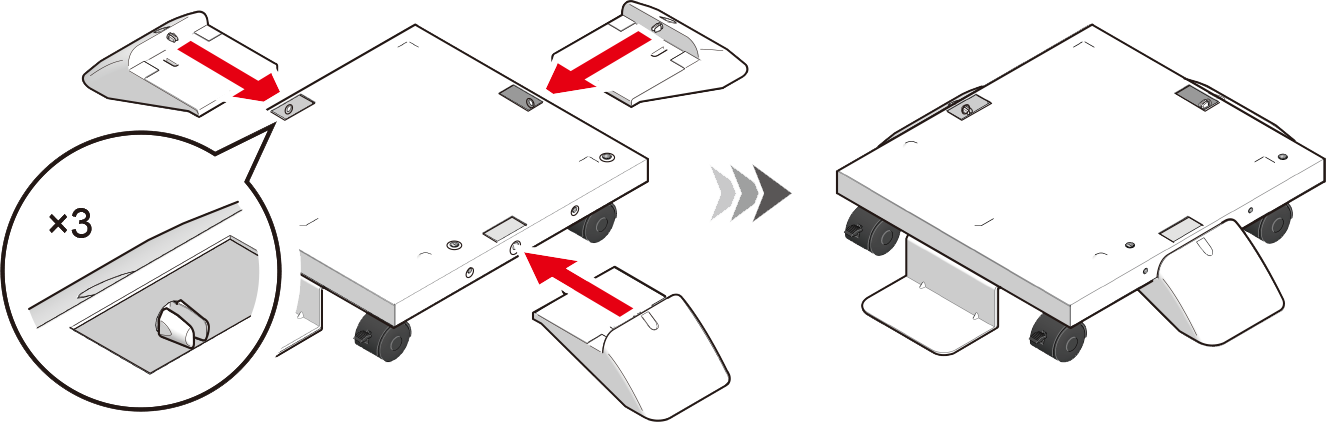
- Check that the anti-tip foot a and the anti-tip feet b (x 3) are inserted in place by turning the dedicated caster stand upside down.
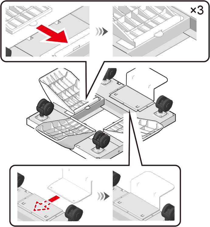
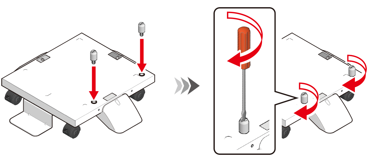
- Turn the dedicated caster stand back and mount the positioning pins (x 2). Rotate to fix the positioning pins (x 2) with a flat-head screwdriver.
Turn off this machine and remove the power cord and all the cables.

- Installation with a cable connected may cause you to get caught in the cable and get injured.
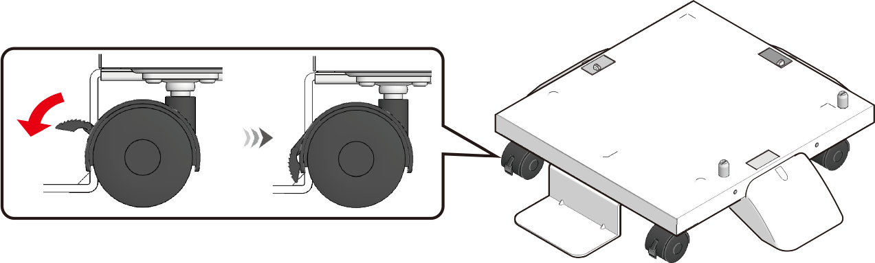
Lock the casters (x 2) to prevent the dedicated caster from moving during the installation of the main unit and the expansion tray.
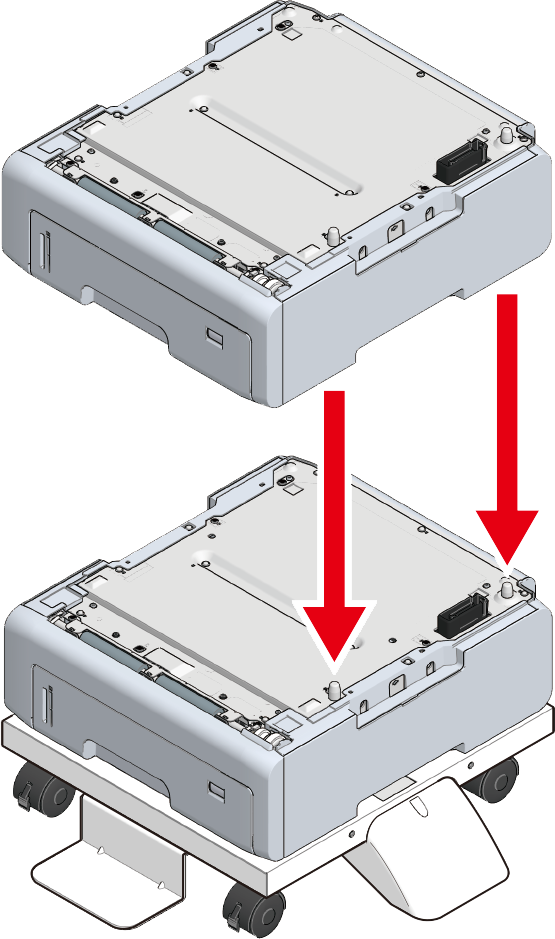
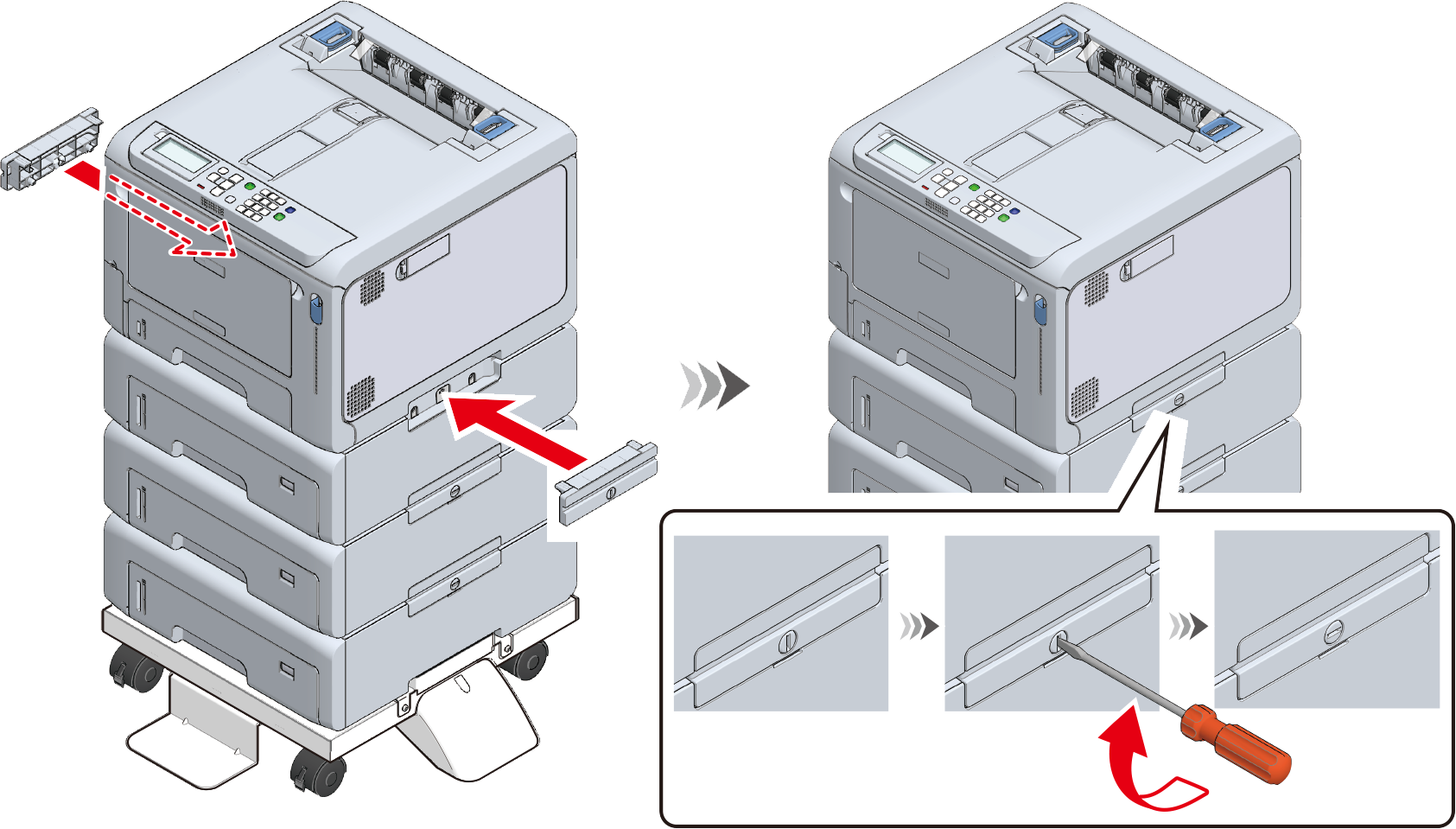
With the main unit or the expansion tray aligned with the dedicated caster on the right side and the front, gently stack them so that the positioning pins of the dedicated caster stand fit into the holes on the bottom.
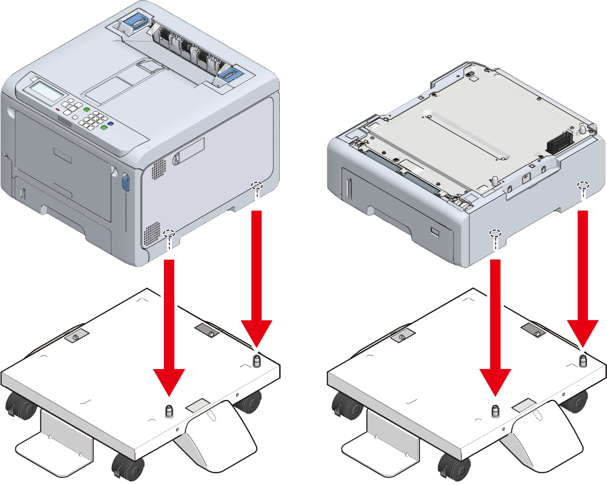
- Fix the main unit or the extension tray and the dedicated caster stand with the metal fixtures (x 2) and the screws (x 4) by using a Phillips-head screwdriver.
The figure shows an example of fixing the expansion tray and the dedicated caster stand.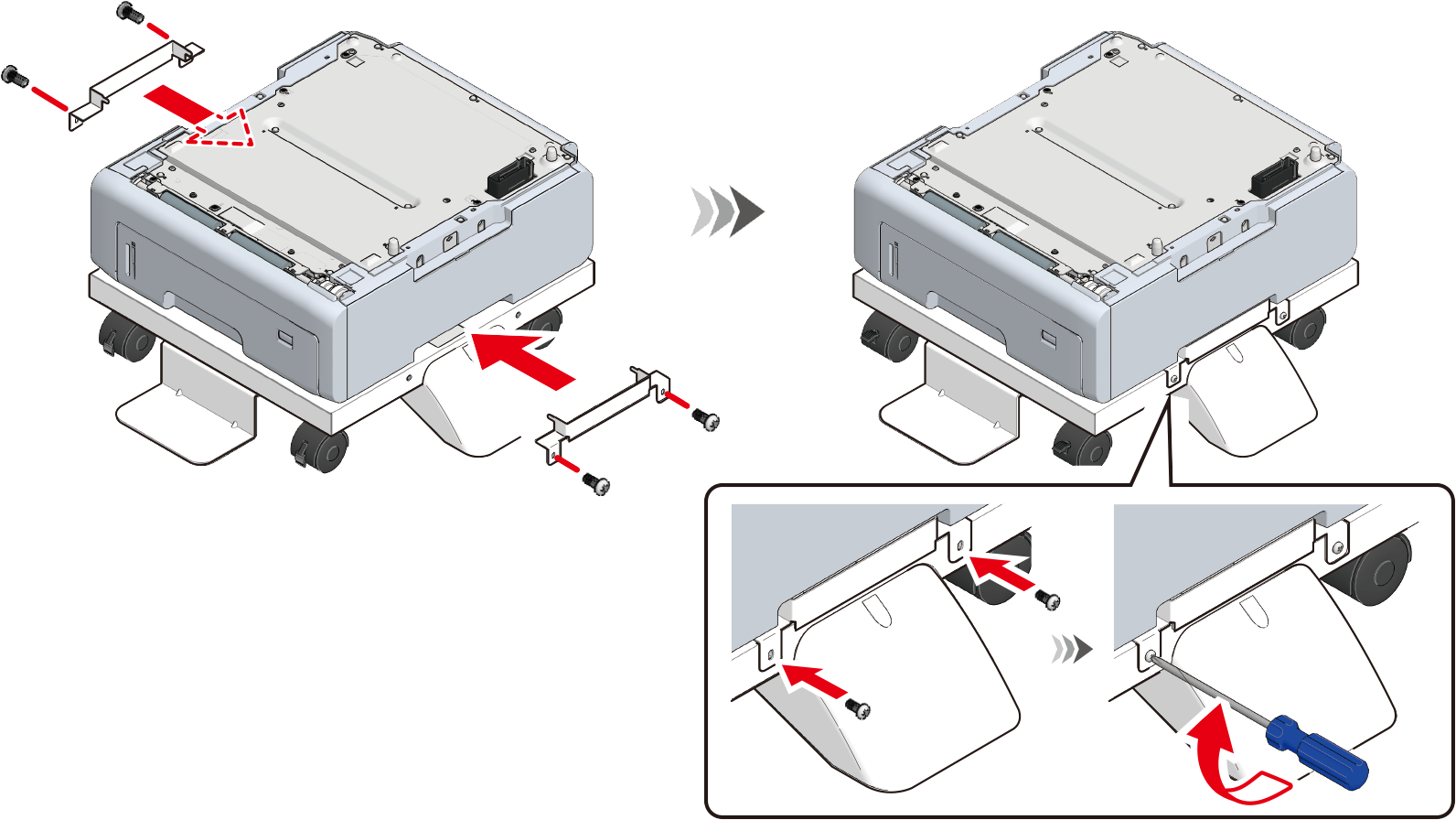
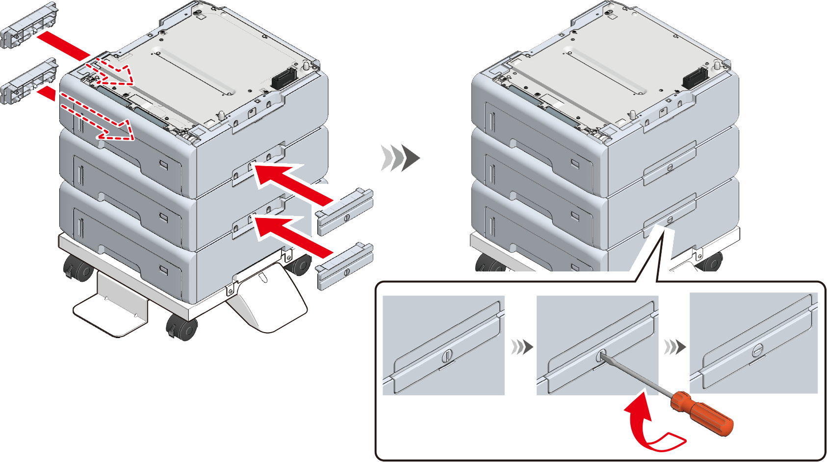
To add more extension trays, with the expansion tray already attached onto the dedicated caster stand aligned with the expansion tray to be installed on the right side and front, gently stack them so that the protrusions fit into the holes on the bottom.
Fix the stacked expansion trays on both sides with accessories by using a flat-head screwdriver.
When multiple expansion trays are installed, with the main unit and the expansion trays aligned on the right side and front, gently stack them so that the protrusions of the expansion tray fit into the holes on the bottom of the main unit.
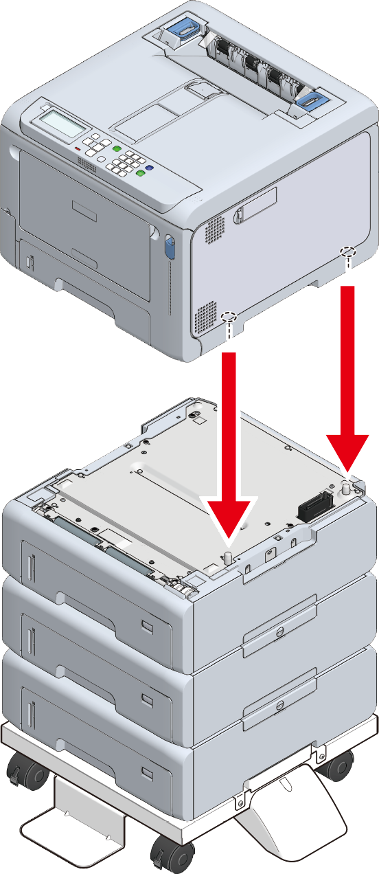
When the expansion tray is installed, fix the main unit and the expansion tray on both sides with accessories by using a flat-head screwdriver.
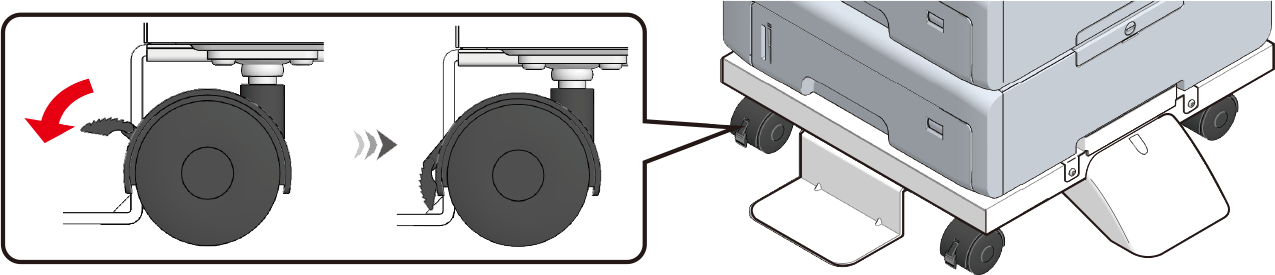
Before moving this machine, unlock the casters (x 2).
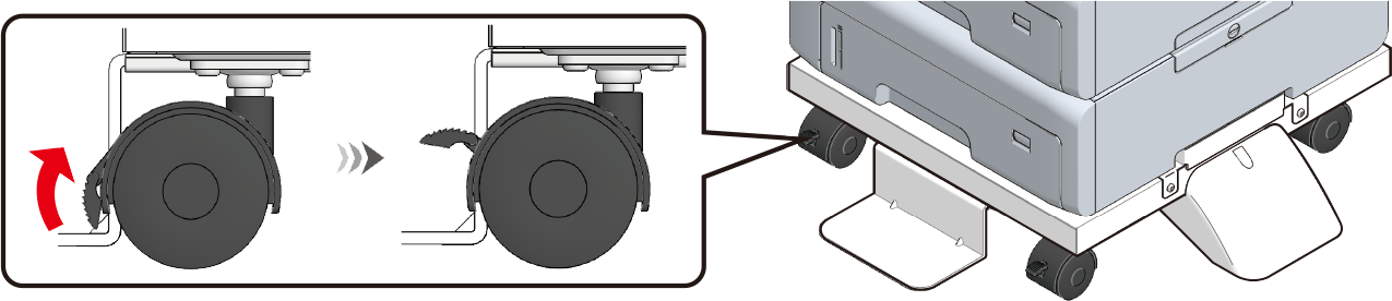
After moving this machine, lock the casters (x 2) to prevent accidental sliding.
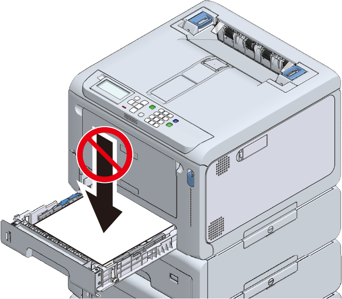
- When transporting this machine, replacing consumables or maintenance items, or loading paper in the tray, check the following points to prevent this machine from toppling.
Do not press on the back of this machine or the image drum basket when the output tray is open and the image drum is pulled out.
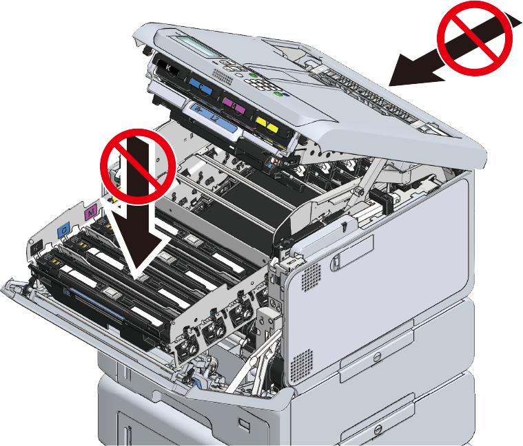
Do not press on the cassette from above when the cassette is pulled out.
- Do not press on this machine from the back with the cassette pulled out.
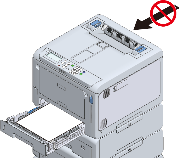
- When transporting this machine, replacing consumables or maintenance items, or loading paper in the tray, check the following points to prevent this machine from toppling.
- Plug in the power cord and the disconnected cable back to this machine.
Power on this machine.
When an expansion tray unit is installed, it is required to check the installation and set the printer driver.